




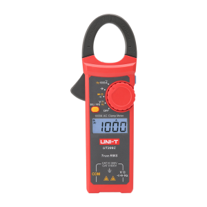

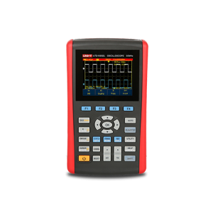

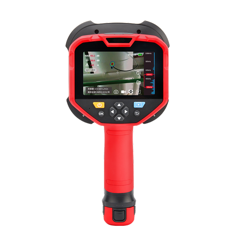

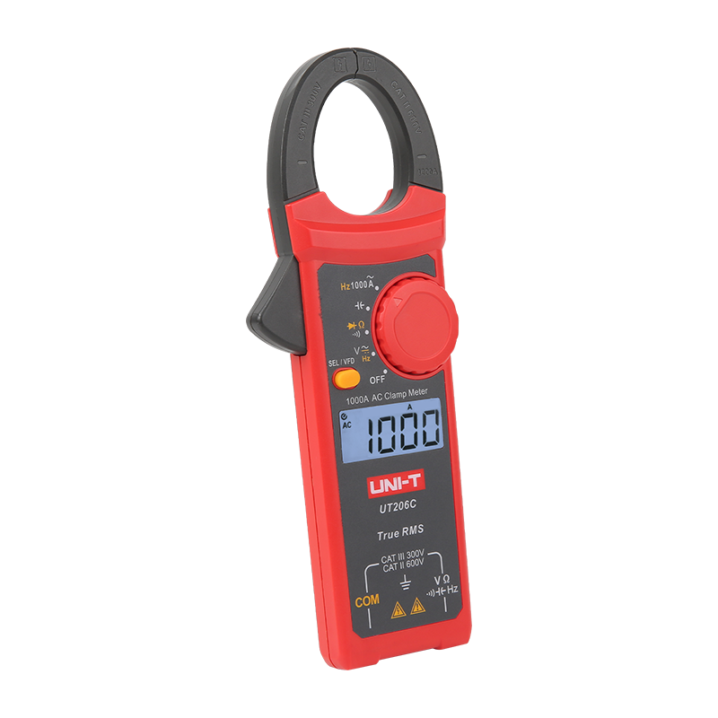

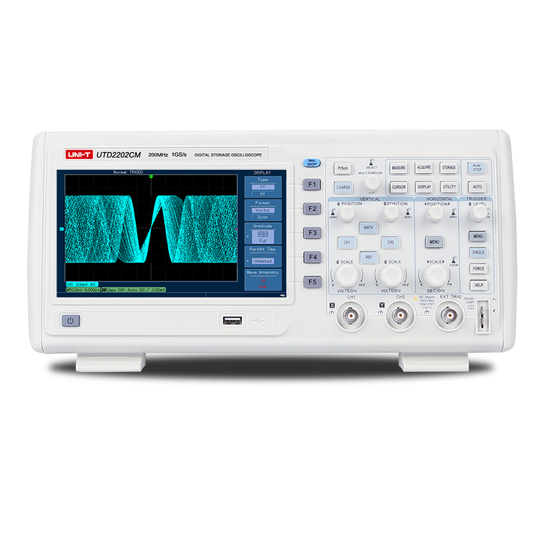


An oscilloscope (also known as scope, oscope, or O-scope) is a test instrument that displays how an electrical signal changes over time, plotting voltage on the vertical axis and time on the horizontal axis. Engineers use it to visualize waveforms and measure amplitude, frequency, and timing, revealing glitches and distortion a multimeter cannot show. Most modern oscilloscopes are digital, capturing signals as sampled data for measurement and analysis. UNI-T builds digital oscilloscopes on this same principle across a range of bandwidths.

Benchtop Instruments
LCR Meters
 Buying Guide
Whether you are a hobbyist, an educator, a developer, or are debugging, performing compliance tests, you need proven measurement technology to be successful. From basic measurements to deep-analysis, UNI-T digital oscilloscopes are built on the same, proven UNI-T technology with product range from MSO oscilloscopes to portable form. You are sure to find the right oscilloscope with an unprecedented price.
Found 4 results

New
New

No products found.
FAQS
Digital Oscilloscopes
An oscilloscope is used to observe, measure, and troubleshoot electrical signals across R&D, education, manufacturing, and field service. Typical tasks include verifying circuit behavior, debugging embedded systems, checking power-supply ripple, decoding serial buses (I²C, SPI, UART, CAN), and validating signal integrity. By showing the exact shape and timing of a signal, it helps engineers confirm a design works and locate faults quickly—the everyday scenarios UNI-T oscilloscopes are designed for.
A digital oscilloscope works by sampling an input signal, converting it to digital data with an analog-to-digital converter (ADC), and reconstructing it as a waveform on screen. The signal enters through a probe, passes through vertical scaling and the ADC, and is stored in acquisition memory. A trigger stabilizes repetitive waveforms so the display stays still, letting you measure voltage and timing accurately—the core acquisition path in every UNI-T digital oscilloscope.
An oscilloscope can measure a wide range of signal parameters, including amplitude (peak-to-peak, RMS), frequency, period, rise and fall time, pulse width, duty cycle, and phase difference between channels. Many models add automated measurements, statistics, FFT/spectrum analysis, and serial-bus decoding. These capabilities let engineers characterize both analog and digital behavior from one instrument—automated measurement and decoding features you’ll also find across UNI-T oscilloscopes.
As a rule of thumb, choose an oscilloscope with bandwidth at least 5× the highest frequency component of your signal, and a sample rate at least 5× that frequency. For digital signals, the scope’s rise time should be 3–5× faster than the signal’s rise time to keep timing error under about 2%. Applying these ratios ensures the captured waveform reflects the real signal—and UNI-T’s oscilloscope range spans multiple bandwidth tiers to match different signal needs.
Analog oscilloscopes display signals directly in real time but cannot store or process data. Digital oscilloscopes sample and store the signal, enabling measurement, math, and analysis—the mainstream type today. Mixed signal oscilloscopes (MSOs) add digital logic channels alongside analog channels, so you can view and correlate analog waveforms with digital buses on the same time base. UNI-T’s lineup includes both digital storage and mixed signal oscilloscopes to suit either workflow.
The primary difference between an MSO (Mixed Signal Oscilloscope) and a UPO (Universal Performance Oscilloscope) is digital signal analysis capability. An MSO combines traditional analog waveform measurement with up to 16 digital logic channels, allowing users to capture and correlate analog and digital signals simultaneously. This makes it ideal for debugging embedded systems, microcontrollers, and serial buses such as SPI, I²C, UART, and CAN. A UPO focuses on high-performance analog measurements and is often a more cost-effective choice for users who only need to analyze analog signals. Choose a UNI-T MSO for mixed-signal debugging and protocol analysis, or a UNI-T UPO for efficient analog testing and troubleshooting.
To choose the right oscilloscope, start from your signal: identify its highest frequency, then apply the 5× bandwidth and sample-rate rules. Next decide how many channels you need, whether you require digital channels (MSO) or serial decoding, and how much record length your captures demand. Finally weigh portability, display, and budget. Matching specifications to the real signal prevents missed glitches and costly rework—and UNI-T’s oscilloscope range is organized by bandwidth and channel count to help you narrow the choice.
To troubleshoot a signal, connect the probe to the test point, adjust the vertical and horizontal scales, configure triggering, and analyze the displayed waveform. UNI-T oscilloscopes provide intuitive controls and automatic measurement tools that simplify signal debugging and fault diagnosis.
High Resolution Oscilloscopes
A high resolution oscilloscope uses advanced analog-to-digital conversion technology to capture waveforms with greater vertical accuracy than conventional oscilloscopes. Compared with standard 8-bit models, high resolution oscilloscopes typically provide 12-bit or higher resolution, allowing users to detect smaller voltage changes and low-level signal details. UNI-T High Resolution Oscilloscopes help engineers perform precise waveform analysis in power electronics, sensor testing, and research applications.
Resolution determines how accurately an oscilloscope converts analog signals into digital waveforms. Higher resolution allows smaller signal variations to be displayed and measured more clearly. This is especially important when analyzing low-noise circuits, power supply ripple, sensor outputs, or other precision signals. UNI-T High Resolution Oscilloscopes provide enhanced waveform visibility for improved measurement confidence.
The main advantages include improved measurement accuracy, reduced quantization noise, better waveform clarity, and enhanced visibility of low-amplitude signals. High resolution oscilloscopes can reveal waveform details that may be difficult to identify on standard oscilloscopes. UNI-T solutions help engineers perform more reliable testing, troubleshooting, and validation in demanding applications.
High resolution oscilloscopes are widely used in power electronics, battery research, semiconductor testing, industrial automation, automotive electronics, sensor development, and scientific laboratories. Their ability to capture subtle waveform variations makes them suitable for applications requiring precise signal analysis and troubleshooting.
The required resolution depends on the signal being measured. For general debugging, 8-bit resolution may be sufficient. However, applications involving small voltage changes, low-level noise analysis, or precision power measurements often benefit from 12-bit or higher resolution. UNI-T High Resolution Oscilloscopes offer enhanced acquisition performance for these demanding measurement tasks.
Yes. High resolution oscilloscopes can capture small voltage fluctuations, switching ripple, and transient events more clearly than standard oscilloscopes. This helps engineers evaluate power quality, optimize converter performance, and identify efficiency issues. UNI-T High Resolution Oscilloscopes provide detailed waveform visibility for power electronics design and validation.
Bandwidth determines the highest signal frequency an oscilloscope can accurately measure, while resolution determines how precisely signal amplitudes can be displayed. Both parameters are important but serve different purposes. UNI-T High Resolution Oscilloscopes combine advanced resolution with strong signal acquisition performance to support accurate waveform analysis.
High resolution oscilloscopes use higher-resolution ADCs and advanced signal processing technologies to improve signal fidelity. By increasing the number of measurable voltage levels, they can reduce quantization effects and display smoother waveforms. This allows engineers to distinguish actual signal behavior from unwanted measurement artifacts.
When selecting a high resolution oscilloscope, consider resolution, bandwidth, sampling rate, channel count, memory depth, and analysis functions. The ideal instrument should match your signal characteristics and testing requirements. UNI-T offers a range of high resolution oscilloscopes designed for laboratory research, product development, and industrial testing applications.
UNI-T High Resolution Oscilloscopes combine precise waveform acquisition, advanced analysis capabilities, and user-friendly operation in a cost-effective solution. Designed for engineers, researchers, and educators, they deliver accurate signal visualization and reliable measurement performance across a wide range of electronic testing applications.
Waveform Generators
A waveform generator is an electronic test instrument used to create electrical signals with specific frequencies, amplitudes, and waveform shapes. Common output signals include sine, square, pulse, ramp, and arbitrary waveforms. Engineers use waveform generators to simulate real-world operating conditions, verify circuit performance, and evaluate electronic devices during design, development, and troubleshooting. UNI-T waveform generators provide flexible signal generation capabilities for research, education, manufacturing, and electronic testing applications.
Waveform generators are used to provide controlled test signals for electronic circuits and systems. Typical applications include amplifier testing, filter characterization, sensor validation, communication system development, and embedded electronics debugging. By generating repeatable signals with precise parameters, a UNI-T waveform generator helps engineers evaluate product performance, identify design issues, and verify system functionality under different operating conditions.
A function generator produces standard waveforms such as sine, square, triangle, and pulse signals. An arbitrary waveform generator (AWG) allows users to create and output customized waveforms that simulate real-world signals or complex test conditions. A waveform generator is a broader category that may include both function generators and AWGs. UNI-T offers solutions ranging from basic function generation to advanced arbitrary waveform generation for diverse testing requirements.
Selecting the right waveform generator depends on factors such as output frequency, waveform type, sampling rate, channel count, modulation capabilities, and application requirements. General-purpose testing may only require standard waveforms, while advanced research or communication development often requires arbitrary waveform generation. UNI-T waveform generators provide multiple performance levels to support education, laboratory, manufacturing, and R&D environments.
Important specifications include maximum output frequency, sample rate, waveform memory depth, vertical resolution, output amplitude range, and modulation functions. Channel synchronization and waveform editing capabilities may also be important for complex applications. Understanding these parameters helps ensure that a UNI-T waveform generator can accurately generate the signals required for your testing and validation tasks.
Waveform memory depth determines how many points can be stored to represent a signal. Greater memory depth allows more complex waveforms and longer signal sequences to be generated without sacrificing detail. This is especially important for communication testing, protocol simulation, and arbitrary waveform generation. UNI-T waveform generators offer powerful waveform storage capabilities to support advanced signal generation requirements.
Signal quality is influenced by parameters such as frequency accuracy, waveform resolution, harmonic distortion, jitter, noise, and output stability. Higher-performance waveform generators provide more accurate and cleaner signals, improving measurement reliability. UNI-T waveform generators are designed to deliver stable signal output and dependable performance across a wide range of electronic testing applications.
Waveform generators are widely used in electronics manufacturing, educational laboratories, communications development, automotive electronics, industrial automation, semiconductor research, and scientific testing. They play an essential role in product design, validation, troubleshooting, and quality control. UNI-T waveform generators provide versatile signal generation capabilities for users across a broad range of industries and applications.
RF Signal Generators
A signal generator is an electronic test instrument that produces controlled electrical signals with defined frequencies, amplitudes, and modulation characteristics. Engineers use signal generators to test, validate, and troubleshoot electronic circuits, communication systems, and RF devices. UNI-T signal generators provide stable and accurate signal output for applications ranging from basic circuit verification to advanced research and development.
Signal generators are commonly used to simulate real-world signals for testing electronic equipment and communication systems. Applications include receiver sensitivity testing, amplifier characterization, RF component validation, wireless communication development, and educational laboratory experiments. UNI-T signal generators help engineers evaluate system performance under repeatable and controlled conditions.
An analog signal generator produces continuous RF or microwave signals with basic modulation capabilities. A vector signal generator can generate digitally modulated signals used in modern wireless communication standards such as LTE, Wi-Fi, Bluetooth, and 5G research. Engineers developing communication devices often choose vector signal generators when complex modulation and protocol testing are required.
Important selection criteria include frequency range, output power level, signal purity, modulation capabilities, frequency accuracy, phase noise, and connectivity options. The ideal signal generator should match the requirements of both current and future testing needs. UNI-T signal generators are available in multiple configurations to support a wide range of measurement applications.
RF signal generators are widely used in wireless communication development, receiver testing, antenna verification, radar research, aerospace electronics, automotive communication systems, and IoT device validation. By providing stable and repeatable RF signals, UNI-T RF signal generators help engineers evaluate device performance and ensure reliable communication system operation.
Signal quality depends on several parameters, including frequency accuracy, phase noise, harmonic distortion, output stability, and modulation performance. Lower noise and higher signal purity generally improve measurement reliability and testing accuracy. UNI-T signal generators are designed to provide consistent signal performance across a wide range of operating conditions.
Spectrum/Signal Analyzers
A spectrum analyzer is an electronic test instrument that displays signal amplitude as a function of frequency. Unlike an oscilloscope, which shows changes in voltage over time, a spectrum analyzer reveals frequency components within a signal. Engineers use UNI-T spectrum analyzers to identify harmonics, spurious emissions, interference sources, and signal distortion in RF, wireless communication, and electronic design applications.
A signal analyzer is used to measure, visualize, and characterize electronic and RF signals. It can help evaluate signal power, frequency, bandwidth, modulation quality, and spectral characteristics. UNI-T signal analyzers are commonly used in wireless communication development, RF testing, product validation, education, and maintenance applications where accurate signal analysis is essential.
A spectrum analyzer focuses on measuring signal power across a frequency range and is widely used for spectrum monitoring, interference detection, and RF troubleshooting. A signal analyzer typically includes additional analysis capabilities, such as modulation and vector signal measurements, allowing deeper evaluation of communication signals. UNI-T offers solutions that support both spectrum analysis and advanced signal characterization requirements.
Spectrum and signal analyzers are used across a variety of industries, including wireless communications, electronics manufacturing, EMC testing, automotive electronics, aerospace, education, and IoT development. They help engineers verify signal quality, identify sources of interference, evaluate transmitter performance, and ensure compliance with technical standards. UNI-T analyzers support both laboratory and field-testing environments.
Selecting the right analyzer depends on your testing requirements, including frequency range, measurement accuracy, signal type, and required analysis functions. Users should also consider sensitivity, dynamic range, phase noise, and portability. UNI-T provides spectrum and signal analyzers designed for applications ranging from basic RF measurements to advanced wireless communication testing.
Important specifications include frequency coverage, resolution bandwidth (RBW), displayed average noise level (DANL), phase noise, dynamic range, sweep speed, and amplitude accuracy. These parameters determine how effectively an analyzer can detect weak signals, resolve closely spaced frequency components, and provide accurate measurements. Choosing the right specifications helps ensure reliable test results.
A real-time spectrum analyzer continuously captures and analyzes signals within a specified bandwidth without measurement gaps. This allows it to detect short-duration, intermittent, or rapidly changing signals that may be missed by conventional swept spectrum analyzers. Real-time spectrum analysis is especially useful for interference hunting, spectrum monitoring, and wireless system troubleshooting.
Sensitivity determines how well an analyzer can detect low-level signals, while dynamic range describes its ability to measure weak signals in the presence of stronger ones. Higher sensitivity and wider dynamic range improve measurement reliability and make it easier to identify small signals, interference, harmonics, and spurious emissions. These characteristics are particularly important in modern RF and wireless testing applications.
Yes. Spectrum analyzers are widely used to evaluate wireless communication signals such as Wi-Fi, Bluetooth, cellular, IoT, and other RF transmissions. They can help measure signal strength, occupied bandwidth, channel behavior, and interference levels. Depending on the model and available functions, UNI-T spectrum analyzers can support a variety of wireless testing and troubleshooting tasks.
A spectrum analyzer displays signals in the frequency domain, showing how signal power is distributed across frequencies, while an oscilloscope displays signals in the time domain, showing voltage changes over time. Both instruments provide valuable but different perspectives of a signal. Engineers often use UNI-T spectrum analyzers and oscilloscopes together to gain a more complete understanding of system performance.
DC Power Supplies
A DC power supply is an instrument that provides stable direct current (DC) voltage and current to power electronic devices, circuits, and systems. Unlike AC power sources, a DC power supply delivers constant output that can be adjusted to meet specific testing or development needs. UNI-T DC power supplies are widely used in laboratories, manufacturing, education, maintenance, and product development environments where reliable and accurate power delivery is essential.
A programmable DC power supply allows users to control voltage, current, and output parameters through a front panel, computer interface, or automated test system. This capability is particularly valuable for repetitive testing, production environments, and R&D applications. UNI-T programmable DC power supplies help improve testing efficiency by enabling automated test sequences, remote operation, data logging, and precise output control.
Selecting the right DC power supply depends on your voltage, current, and power requirements. Users should also consider output accuracy, programming capabilities, channel count, form factor, and future expansion needs. For laboratory use, flexibility and ease of operation may be important, while automated testing environments often require remote control and programmable functions. UNI-T offers a wide range of DC power supplies to support different testing and development applications.
Key specifications include output voltage range, maximum current, rated power, load regulation, line regulation, ripple and noise, programming resolution, and measurement accuracy. Additional features such as multiple outputs, interface options, and protection functions may also be important. Understanding these specifications helps ensure the selected UNI-T DC power supply can provide the performance and reliability required for your specific application.
Linear DC power supplies are known for low noise, excellent regulation, and clean output signals, making them suitable for sensitive analog and laboratory applications. Switching DC power supplies are generally smaller, lighter, and more efficient, delivering higher power density while generating less heat. The best choice depends on your application requirements, balancing output quality, efficiency, size, and cost considerations.
An autoranging DC power supply automatically adjusts the relationship between voltage and current within its maximum power rating. Unlike traditional fixed-range supplies, it provides greater flexibility by delivering different voltage-current combinations without requiring users to switch operating ranges. UNI-T autoranging power supplies allow engineers to test a wider variety of devices using a single instrument, improving efficiency and reducing equipment requirements.
Yes. Many DC power supplies can be used to simulate battery output by providing stable and adjustable DC voltage levels. This allows engineers to evaluate products without using physical batteries during development and testing. Battery simulation is commonly used in consumer electronics, automotive electronics, IoT devices, and power management applications where consistent and repeatable power conditions are required.
Multiple DC power supplies can often be connected in series to increase total output voltage or in parallel to increase available output current. Series connections combine voltage levels while maintaining the same current rating, whereas parallel connections increase current capacity while maintaining the same output voltage. Before configuring power supplies in this manner, users should verify that the instruments support series or parallel operation and follow the manufacturer’s recommendations.
A single-channel DC power supply provides one independent output and is ideal for powering individual devices or simple test setups. A multi-channel DC power supply offers two or more independently controllable outputs, allowing multiple circuits or voltage rails to be powered simultaneously. UNI-T multi-channel DC power supplies are particularly useful for embedded systems, mixed-signal designs, educational laboratories, and development environments where several power sources are required.
Ripple and noise represent unwanted fluctuations superimposed on a DC output signal. Excessive ripple and noise can affect measurement accuracy, interfere with sensitive circuits, and introduce errors during testing. Low ripple and noise performance is especially important when working with precision analog circuits, sensors, communication systems, and research applications. Choosing a DC power supply with low output noise helps improve test reliability and overall system performance.
DC Electronic Loads
A DC electronic load is a programmable test instrument designed to draw power from a DC source while controlling voltage, current, resistance, or power according to predefined settings. Unlike passive resistors, electronic loads can simulate real operating conditions and provide accurate measurements during testing. UNI-T DC electronic loads are widely used for evaluating power supplies, batteries, chargers, fuel cells, and DC-DC converters in research, development, manufacturing, and quality assurance environments.
DC electronic loads are used to test and characterize DC power sources under controlled load conditions. They help engineers measure performance, efficiency, stability, protection behavior, and load regulation. Common applications include power supply testing, battery discharge analysis, charger validation, solar energy evaluation, and converter verification. UNI-T DC electronic loads provide flexible test capabilities for both laboratory development and production testing environments.
A resistor provides a fixed load, while an electronic load offers precise and programmable control over current, voltage, resistance, or power. This allows engineers to simulate real-world operating conditions that change over time. Electronic loads can also automate testing and provide detailed measurements, making them more effective for modern product development and validation. UNI-T DC electronic loads offer greater flexibility, accuracy, and efficiency than traditional resistive load methods.
Most DC electronic loads support multiple operating modes, including Constant Current (CC), Constant Voltage (CV), Constant Resistance (CR), and Constant Power (CP). CC mode maintains a fixed current regardless of voltage changes, while CV mode regulates voltage. CR mode simulates a fixed resistance, and CP mode maintains constant power consumption. These operating modes allow UNI-T DC electronic loads to support a wide variety of testing scenarios for batteries, power supplies, and power conversion devices.
The ideal DC electronic load depends on the voltage, current, and power levels of the device being tested. Users should also consider operating modes, measurement accuracy, transient performance, programming capabilities, and interface options. Applications such as battery testing, power supply validation, and converter development may require different specifications. UNI-T offers a broad range of DC electronic loads to meet various testing requirements across R&D, manufacturing, and education.
Important specifications include maximum voltage, maximum current, power rating, operating modes, measurement accuracy, resolution, and transient response speed. Additional factors such as programmable functions, communication interfaces, data logging, and protection features may also influence the selection process. Choosing a UNI-T DC electronic load with the appropriate specifications helps ensure reliable testing, accurate measurements, and efficient workflow integration.
DC electronic loads can simulate various load conditions to evaluate how power devices perform in real applications. Engineers use them to verify voltage regulation, current capability, efficiency, protection functions, and thermal performance. During battery testing, electronic loads enable controlled discharge cycles, while in DC-DC converter testing they help assess transient response and stability. UNI-T DC electronic loads provide repeatable and accurate load conditions for comprehensive power device evaluation.
AC Power Sources
An AC power source is a test instrument that provides controlled AC voltage and frequency to power and evaluate electronic products, components, and systems. Unlike standard utility power, an AC power source allows users to precisely adjust output parameters and simulate different operating conditions. UNI-T AC power sources are widely used for product development, validation, manufacturing, and compliance testing in applications where stable and programmable AC power is required.
Choosing the right AC power source depends on the electrical requirements of the device under test, including voltage range, frequency range, power capacity, phase configuration, and test objectives. Users should also consider programming capabilities, measurement accuracy, and future testing needs. UNI-T AC power sources are available in a variety of configurations to support applications ranging from consumer electronics testing to industrial and renewable energy validation.
Key specifications include output voltage range, frequency range, power rating, current capability, voltage regulation, frequency accuracy, and total harmonic distortion (THD). Additional features such as programmable output sequences, waveform generation, measurement functions, and communication interfaces may also be important depending on the application. Selecting the appropriate specifications helps ensure accurate testing and reliable performance evaluation.
AC power sources are commonly used to test consumer electronics, household appliances, AC-DC power supplies, industrial equipment, EV chargers, renewable energy systems, motors, and telecommunications equipment. By providing stable and programmable AC input power, they allow engineers to verify product behavior across different operating conditions and power standards used around the world.
Digital Multimeters
A bench digital multimeter (DMM) is a high-accuracy measurement instrument designed for laboratory, production, and automated test applications. Compared with handheld multimeters, bench DMMs typically offer higher precision, better resolution, faster reading rates, and advanced connectivity options. UNI-T bench digital multimeters provide reliable measurements for voltage, current, resistance, frequency, and other electrical parameters in demanding testing environments.
A bench digital multimeter can perform a wide range of electrical measurements, including DC voltage, AC voltage, DC current, AC current, resistance, frequency, continuity, and diode testing. Some models also support capacitance, temperature, and advanced measurement functions. UNI-T bench DMMs combine multiple measurement capabilities in a single instrument, helping engineers improve test efficiency and reduce equipment requirements.
Accuracy describes how close a measurement is to the true value, while resolution refers to the smallest change the instrument can detect and display. A multimeter may provide high resolution without necessarily delivering high accuracy. When selecting a UNI-T bench digital multimeter, both specifications should be considered to ensure the instrument provides meaningful and reliable measurements for the intended application.
Handheld multimeters are portable and well suited for field service, maintenance, and troubleshooting tasks. Bench digital multimeters are designed for laboratory and production environments where higher accuracy, better resolution, faster measurement speed, and automated testing capabilities are required. UNI-T bench DMMs also offer larger displays, remote-control interfaces, and data logging functions that are not typically available in handheld models.
The ideal bench digital multimeter depends on your application requirements, including measurement accuracy, resolution, reading speed, connectivity options, and supported measurement functions. Research laboratories may prioritize precision and stability, while manufacturing environments often require high throughput and automation capabilities. UNI-T offers bench DMM solutions suitable for education, R&D, production testing, and quality control applications.
Important specifications include accuracy, resolution, display digits, reading rate, input impedance, measurement functions, and communication interfaces. Users should also consider long-term stability, data logging capabilities, and integration requirements for automated test systems. Understanding these parameters helps ensure the selected UNI-T bench digital multimeter meets both current and future measurement needs.
Reading speed determines how quickly a multimeter can acquire and display measurements, while accuracy affects the reliability of measurement results. Faster reading rates can significantly improve productivity in automated testing and production environments, while high accuracy is critical for research, calibration, and precision measurement tasks. UNI-T bench digital multimeters are designed to balance measurement speed and accuracy for a wide range of testing applications.
Yes. Many bench digital multimeters support communication interfaces such as USB, LAN, RS-232, or other remote-control options, allowing them to be integrated into automated test environments. Combined with software control and data acquisition systems, UNI-T bench DMMs can help improve testing efficiency, reduce human error, and support consistent measurement procedures in laboratories and production lines.
Common measurement errors can result from improper test lead connections, incorrect measurement ranges, poor contact resistance, environmental noise, temperature variations, or operator mistakes. Regular calibration, proper instrument setup, and following recommended measurement practices can help minimize these errors. UNI-T bench digital multimeters are designed to support stable and repeatable measurements in professional testing environments.
Modern bench digital multimeters should provide high accuracy, reliable measurement performance, multiple measurement functions, fast reading rates, and convenient connectivity options. Features such as data logging, remote control, large displays, statistical analysis functions, and automated testing support can further improve productivity. Selecting a UNI-T bench DMM with the right combination of performance and functionality can help meet both routine and advanced measurement requirements.
LCR Meters
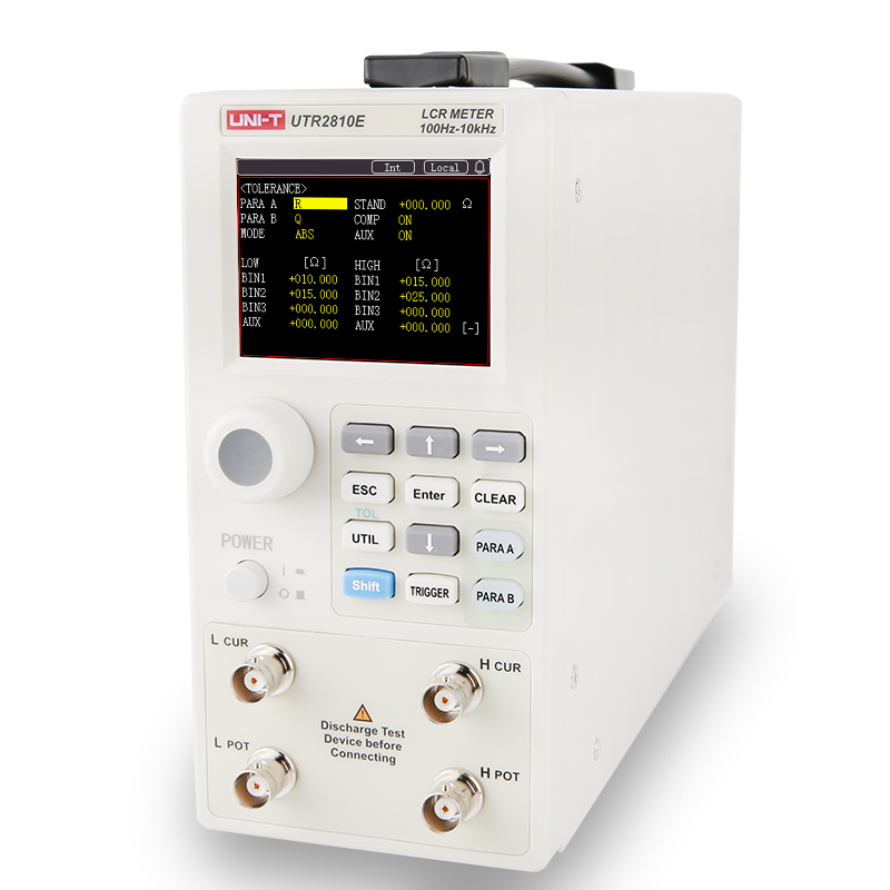
An LCR meter is designed to measure the electrical properties of passive components, including inductance (L), capacitance (C), and resistance (R). Depending on the model, it can also measure related parameters such as impedance, quality factor (Q), dissipation factor (D), phase angle, and ESR. UNI-T LCR meters help engineers evaluate component performance, verify specifications, and support quality control in research, development, and manufacturing environments.
LCR meters are widely used for testing and characterizing electronic components during design, production, incoming inspection, and troubleshooting. Engineers use them to verify capacitor values, measure inductance in coils and transformers, evaluate resistor performance, and identify component degradation. UNI-T LCR meters are suitable for laboratories, production lines, educational institutions, and maintenance applications where accurate component analysis is required.
Choosing the right LCR meter depends on the types of components being tested, required measurement accuracy, test frequency range, and production or laboratory requirements. Users should consider factors such as measurement speed, parameter support, bias capabilities, interface options, and automation requirements. UNI-T offers LCR meters with a range of performance levels to support research, quality control, and high-volume production testing.
Important specifications include measurement accuracy, test frequency range, measurement speed, basic accuracy, test signal level, and supported measurement parameters. Users may also consider fixture compatibility, communication interfaces, and data storage capabilities. Understanding these specifications helps ensure the selected UNI-T LCR meter can provide reliable and repeatable measurements for both current and future testing requirements.
LCR meters can be used to test a wide variety of passive components, including capacitors, inductors, resistors, transformers, coils, ferrite devices, filters, connectors, switches, and other electronic materials. They are commonly used for component verification, incoming inspection, failure analysis, and production quality control. UNI-T LCR meters help users perform accurate and efficient measurements across a broad range of component testing applications.
The electrical characteristics of many components vary with frequency, making test frequency one of the most important factors in LCR measurements. For example, capacitance, inductance, impedance, ESR, and Q factor may produce different results at different frequencies. Selecting the appropriate test frequency helps engineers obtain measurement data that more accurately reflects actual operating conditions and application performance.
Both test frequency and bias conditions can significantly influence measurement results. Many components behave differently when subjected to varying frequencies or DC bias voltages, especially capacitors, inductors, and magnetic materials. Using test conditions that closely match real operating environments helps improve measurement relevance and consistency. UNI-T LCR meters support precise test parameter control to help users obtain more meaningful component characterization data.
Measurement accuracy can be improved by using appropriate test fixtures, selecting the correct test frequency, performing regular calibration, minimizing external interference, and ensuring proper component connections. Environmental conditions such as temperature and humidity may also affect results. Following recommended measurement practices and using a properly configured UNI-T LCR meter can help deliver more stable, repeatable, and reliable measurements.
Battery Testers
A battery tester measures key electrical parameters that help assess battery condition and performance. UNI-T battery testers are designed to simultaneously measure battery internal resistance and DC voltage, providing a fast and reliable way to evaluate battery quality and health. By analyzing these parameters together, users can identify deteriorating batteries, detect inconsistencies within battery packs, and support quality control processes in battery production, maintenance, and research environments.
Internal resistance is one of the most important indicators of battery condition. As a battery ages or degrades, its internal resistance typically increases, reducing efficiency and power delivery capability. Measuring internal resistance helps identify weak or aging cells before significant performance issues occur. UNI-T battery testers provide accurate internal resistance measurements that support battery screening, quality inspection, preventive maintenance, and performance evaluation across a variety of battery types.
Battery health is commonly evaluated by measuring both battery voltage and internal resistance. Voltage indicates the current electrical state of the battery, while internal resistance provides insight into aging, degradation, and power delivery capability. By comparing these measurements against expected values, engineers and maintenance personnel can identify abnormal cells, assess battery condition, and make informed decisions about replacement or further testing. UNI-T battery testers enable fast and repeatable battery health assessments.
UNI-T battery testers support a wide range of battery technologies used in industrial, commercial, and consumer applications. Depending on the model, they can be used to test lithium-ion batteries, lead-acid batteries, NiMH batteries, NiCd batteries, button cells, battery modules, and battery packs. Their broad measurement ranges and high accuracy make them suitable for battery manufacturing, maintenance, quality control, and research applications.
Internal resistance directly affects a battery’s ability to deliver power efficiently. Batteries with lower internal resistance can typically provide higher current with less energy loss, while increased internal resistance may result in voltage drops, reduced efficiency, excessive heat generation, and shorter operating life. Monitoring internal resistance helps users evaluate battery consistency, detect degradation trends, and maintain reliable performance in critical applications such as UPS systems, energy storage, and portable devices.
The right battery tester depends on the battery types, test environment, accuracy requirements, and workflow needs. Portable instruments may be ideal for field inspections and maintenance, while benchtop models are often preferred for laboratory analysis, battery production, and automated testing. Users should also consider voltage range, resistance range, measurement speed, connectivity options, and automation capabilities. UNI-T offers both handheld and benchtop battery testers to support diverse testing applications.
Handheld battery testers are designed for portability and on-site inspections, making them suitable for maintenance, field service, and battery system troubleshooting. Benchtop battery testers typically offer higher measurement speed, expanded connectivity, automated testing support, and easier integration into production environments. UNI-T handheld battery testers provide flexible field measurements, while benchtop battery testers support battery R&D, incoming inspection, quality control, and high-volume manufacturing applications.
Yes. Battery testers are widely used in production and quality control processes to verify battery consistency and performance before products are shipped. Fast measurement speed and automated operation help improve testing efficiency while reducing the risk of defective cells entering finished products. UNI-T benchtop battery testers support industrial applications through features such as remote control, communication interfaces, automated test integration, and high-speed measurement capabilities.
Several factors can influence internal resistance measurements, including battery state of charge, temperature, measurement method, contact resistance, and test conditions. Variations in these factors may cause differences in measurement results even for the same battery. To achieve consistent and reliable data, testing should be performed using appropriate fixtures, stable environmental conditions, and standardized procedures. Accurate measurement practices help improve battery evaluation and quality assessment.
Testing frequency depends on battery type, operating conditions, and application requirements. Batteries used in critical systems such as UPS installations, backup power systems, telecommunications equipment, and energy storage systems often require regular condition monitoring to ensure reliability. Routine testing of voltage and internal resistance can help identify deteriorating batteries before failures occur. Regular battery testing supports preventive maintenance programs and helps extend overall system reliability.
Micro Ohm Meters
A micro ohm meter is a precision instrument designed to measure extremely low resistance values, typically in the micro-ohm (μΩ) and milli-ohm (mΩ) range. Unlike standard multimeters, which are intended for general resistance measurements, micro ohm meters are optimized for high accuracy and repeatability when testing conductive paths and electrical connections. UNI-T micro ohm meters help engineers evaluate connection integrity, detect resistance increases, and verify the quality of electrical components and assemblies.
Micro ohm meters are used whenever highly accurate low-resistance measurements are required. Common applications include testing busbars, cables, connectors, circuit breakers, relay contacts, switch contacts, grounding systems, transformer windings, and motor windings. By measuring small resistance changes that may not be visible with conventional instruments, UNI-T micro ohm meters help identify poor connections, material degradation, and manufacturing defects before they affect system performance.
Low-resistance measurements can reveal issues that may lead to excessive heating, energy loss, voltage drops, or equipment failure. Even a small increase in contact resistance can significantly affect the performance and reliability of power distribution systems and electrical equipment. Accurate low-resistance testing helps engineers verify component quality, monitor system health, and detect developing problems at an early stage, reducing maintenance costs and improving operational reliability.
A standard multimeter can measure resistance, but its accuracy and resolution may not be sufficient for very low resistance values. Lead resistance and contact resistance can significantly influence measurements when testing in the micro-ohm range. A UNI-T micro ohm meter is specifically designed for low-resistance measurements and typically uses four-wire Kelvin measurement techniques to eliminate test lead resistance effects, providing more accurate and reliable results for critical applications.
Four-wire Kelvin measurement uses separate pairs of leads for current injection and voltage sensing. This method minimizes errors caused by lead resistance and connection resistance, which can significantly affect low-resistance measurements. By isolating the voltage measurement from the current path, a micro ohm meter can achieve much higher accuracy than a conventional two-wire measurement. Kelvin measurement is widely used in electrical testing, production inspection, and quality control applications.
Micro ohm meters can be used to test a broad range of conductive components and systems, including cables, connectors, busbars, relay contacts, switch contacts, circuit breakers, grounding conductors, battery connections, transformers, motor windings, and welded joints. These measurements help verify manufacturing quality, evaluate electrical continuity, and identify abnormal resistance that could affect performance, efficiency, or safety.
Selecting a micro ohm meter depends on the resistance range, accuracy requirements, test current capability, portability needs, and application environment. Users should also consider measurement speed, data storage functions, communication interfaces, and support for automated testing. UNI-T micro ohm meters are available for field maintenance, laboratory measurements, production line testing, and electrical equipment inspection where precise low-resistance measurements are required.
Measurement accuracy can be influenced by lead resistance, contact quality, test current stability, temperature variations, oxidation, vibration, and environmental interference. Poor connections and unstable test conditions may introduce measurement errors, especially when testing very small resistance values. Using proper fixtures, clean contact surfaces, and appropriate measurement techniques can help improve consistency and measurement confidence.
Yes. Micro ohm meters are commonly used in manufacturing and quality control processes to verify electrical connections and component consistency. They can quickly identify high-resistance connections, poor welds, faulty contacts, and assembly defects before products leave the factory. UNI-T micro ohm meters help improve product reliability, reduce failure rates, and support efficient inspection procedures in production environments.
To achieve the most accurate results, users should use four-wire Kelvin measurement whenever possible, ensure clean and secure connections, maintain stable environmental conditions, and follow recommended calibration procedures. Proper test current selection and appropriate test fixtures can also improve measurement reliability. Regular instrument verification and consistent testing practices help ensure accurate, repeatable low-resistance measurements across different applications.
Power Meters
A power meter is an instrument used to measure and analyze electrical power parameters in AC and DC systems. Unlike basic voltage or current measuring devices, a power meter can simultaneously measure voltage, current, power, frequency, and power factor to provide a more complete view of system performance. UNI-T power meters are designed for product testing, quality control, research, and production environments where accurate electrical parameter measurements are required.
Modern power meters can measure multiple electrical parameters at the same time, including voltage, current, active power, apparent power, power factor, frequency, and RMS values. Depending on the application, these measurements help engineers evaluate energy consumption, power conversion efficiency, and overall system performance. UNI-T power meters provide comprehensive electrical measurements that simplify testing and analysis across a wide range of applications.
A digital multimeter is primarily used to measure individual electrical parameters such as voltage, current, or resistance. A power meter is specifically designed to analyze power-related characteristics by measuring multiple electrical parameters simultaneously and calculating power values in real time. UNI-T power meters provide a more complete understanding of electrical system performance, making them ideal for power analysis, efficiency testing, and product validation.
Selecting the right power meter depends on the voltage range, current range, measurement bandwidth, accuracy requirements, and application type. Laboratory testing, manufacturing, and product development may require different performance levels and interface options. UNI-T power meters are available with various measurement capabilities to support applications ranging from routine electrical testing to advanced power analysis and automated production testing.
Important specifications include voltage range, current range, measurement accuracy, bandwidth, resolution, sampling performance, and communication interfaces. Users should also consider supported measurement functions, display capabilities, data logging options, and automation requirements. Choosing a power meter with the appropriate specifications helps ensure reliable measurements and efficient workflow integration for both current and future testing needs.
Power factor indicates how effectively electrical power is being converted into useful work. A low power factor may result in reduced efficiency, increased energy costs, and additional stress on electrical equipment. Measuring power factor helps engineers evaluate system efficiency, identify performance issues, and optimize equipment operation. UNI-T power meters provide accurate power factor measurements for power supply testing, industrial equipment analysis, and energy efficiency evaluation.
Power meters are widely used in power supply testing, appliance evaluation, motor testing, energy efficiency analysis, electronics manufacturing, research laboratories, and quality control processes. They help engineers measure power consumption, verify product performance, and evaluate electrical characteristics under different operating conditions. UNI-T power meters support a broad range of applications where accurate electrical parameter measurements are essential.
Yes. Many modern power meters support communication interfaces such as USB, LAN, RS-232, or GPIB, allowing them to be integrated into automated test systems and production environments. Combined with software control and data acquisition systems, UNI-T power meters can support automated measurements, data collection, and test sequence execution, helping improve productivity and measurement consistency.
Accurate power measurements depend on proper instrument setup, correct wiring methods, stable test conditions, and regular calibration practices. Users should select suitable voltage and current ranges, minimize external noise sources, and ensure secure electrical connections. Following recommended measurement procedures and using a properly configured UNI-T power meter can help achieve consistent and reliable results in both laboratory and production environments.
Modern digital power meters should provide high measurement accuracy, wide bandwidth, multi-parameter analysis, intuitive operation, and flexible connectivity options. Features such as graphical displays, data logging, multi-channel measurement, remote control, and automated testing support can improve efficiency and simplify power analysis tasks. Selecting a UNI-T power meter with the right combination of performance and functionality helps support both routine measurements and advanced electrical testing applications.
Data Loggers
A data logger is an instrument used to automatically collect, store, and monitor measurement data over time. It can continuously record parameters such as temperature, voltage, current, humidity, and other process signals without requiring constant user supervision. UNI-T data loggers combine multi-channel acquisition, real-time monitoring, and long-term data storage, helping users capture critical measurement data for analysis, validation, and troubleshooting.
Data loggers can measure a wide range of physical and electrical parameters depending on the installed modules and sensors. Common measurements include temperature, voltage, current, humidity, and process signals from thermocouples, RTDs, and industrial sensors. UNI-T data loggers support flexible measurement configurations, allowing users to monitor multiple types of signals simultaneously within a single platform.
Data loggers are used to monitor and record data continuously in applications where trends and long-term performance are important. Common applications include laboratory research, environmental monitoring, product testing, industrial process control, equipment validation, and quality assurance. UNI-T data loggers help users identify system behavior, track performance changes, and generate reliable historical records for analysis and reporting.
Selecting the right data logger depends on the number of required channels, measurement types, sampling speed, storage capacity, and communication requirements. Users should also consider expansion capability, software support, and long-term monitoring needs. UNI-T data loggers provide scalable solutions that support everything from basic temperature monitoring to complex multi-channel data acquisition applications.
Important specifications include channel count, measurement accuracy, supported sensor types, scanning speed, storage capacity, communication interfaces, and operating temperature range. Additional factors such as alarm functions, trend display, remote monitoring, and data export capabilities may also be important. Selecting the right specifications helps ensure the data logger meets both current and future monitoring requirements.
A data logger focuses on automated data collection, storage, and long-term monitoring, while a data acquisition system often emphasizes high-speed measurement, signal processing, and real-time analysis. Modern UNI-T data loggers combine many features traditionally associated with data acquisition systems, including multi-channel measurement, real-time display, communication interfaces, and flexible expansion capabilities.
Multi-channel data logging allows users to monitor multiple sensors, devices, or locations simultaneously from a single instrument. This improves efficiency, reduces equipment requirements, and provides a more complete view of system performance. UNI-T multi-channel data loggers support synchronized measurements across many channels, making them ideal for thermal testing, environmental monitoring, process validation, and industrial automation applications.
Yes. Data loggers are specifically designed for long-term monitoring applications where measurements must be recorded continuously over extended periods. They can automatically collect data, track historical trends, store alarm events, and generate records for later analysis. UNI-T data loggers provide reliable long-term data acquisition for laboratory experiments, environmental studies, equipment monitoring, and production processes.
Hipot Testers
A hipot tester, also known as a dielectric withstand tester, is an electrical safety instrument used to verify whether insulation can safely withstand high-voltage stress without breakdown. By applying a controlled high voltage between conductive parts and insulation barriers, the tester detects excessive leakage current that may indicate insulation defects. UNI-T hipot testers help manufacturers validate product safety, insulation integrity, and compliance requirements across a wide range of electrical and electronic products.
A hipot test is used to evaluate the insulation strength of electrical products and ensure they can operate safely under specified voltage conditions. It helps identify manufacturing defects, insulation weaknesses, contamination, or material degradation that could lead to electrical shock, fire hazards, or premature product failure. Hipot testing is widely performed during product development, production testing, quality control, and routine safety verification.
AC and DC hipot testing serve the same purpose but use different test voltages. AC hipot testing stresses both the resistive and capacitive characteristics of insulation and is commonly used for general electrical safety verification. DC hipot testing typically generates lower leakage currents and may be preferred for products with high capacitance or applications where controlled leakage measurements are important. The choice depends on product design, applicable standards, and testing requirements.
The right hipot tester depends on factors such as required test voltage, leakage current range, product type, testing standards, and production requirements. Users should consider whether AC, DC, or both testing modes are needed, as well as measurement accuracy, automation capabilities, and interface options. UNI-T hipot testers are available for applications ranging from component testing and transformer verification to appliance manufacturing and industrial production environments.
Important specifications include maximum test voltage, leakage current measurement range, current resolution, accuracy, output capacity, and safety protection features. Communication interfaces, automation support, and test result management functions may also influence the selection process. Choosing a hipot tester with suitable specifications helps ensure reliable insulation testing, efficient operation, and compliance with product safety requirements.
Hipot testers are used to verify the electrical safety of a broad range of products, including household appliances, transformers, power supplies, cables, motors, electrical components, industrial equipment, and electronic assemblies. Any product that relies on insulation to separate conductive parts may require hipot testing during development or manufacturing. These tests help ensure safe operation and reliable performance throughout the product lifecycle.
Insulation integrity is essential for protecting users and equipment from electrical hazards. Damaged, contaminated, or inadequate insulation can lead to current leakage, electric shock risks, short circuits, or equipment failure. Verifying insulation integrity through high-voltage testing helps manufacturers identify potential weaknesses before products reach the market. Strong insulation performance also contributes to product reliability, durability, and regulatory compliance.
Leakage current levels vary depending on the product type, operating voltage, insulation design, and applicable safety standards. In general, unexpectedly high leakage current during a hipot test may indicate insulation defects, contamination, moisture intrusion, or insufficient insulation spacing. Rather than relying on a single universal limit, manufacturers typically establish acceptable thresholds based on product specifications and regulatory requirements. Consistent monitoring of leakage current trends can help detect developing insulation issues before they become critical failures.
Insulation Resistance Testers
An insulation resistance tester is an instrument used to evaluate the quality and condition of electrical insulation by applying a DC test voltage and measuring the resulting resistance. High insulation resistance generally indicates good insulation performance, while lower values may suggest contamination, moisture ingress, aging, or insulation damage. UNI-T insulation resistance testers help users verify electrical safety, product reliability, and insulation integrity across a wide range of applications.
Insulation resistance testing is used to assess the ability of insulation materials to prevent unwanted current leakage between conductors and ground. It is commonly performed during equipment maintenance, product development, quality inspection, and manufacturing processes. Engineers use insulation resistance testing to identify insulation degradation before it leads to equipment failure, electrical hazards, or reduced system reliability.
An insulation resistance tester applies a controlled DC voltage to the device or material under test and measures the leakage current that flows through the insulation. Using Ohm’s law, the instrument calculates the insulation resistance value based on the applied voltage and measured current. UNI-T insulation resistance testers provide stable test voltages and precise measurements to support accurate insulation evaluation across different products and materials.
Although both methods evaluate electrical insulation, they serve different purposes. Insulation resistance testing measures the resistance of insulation under a specified DC voltage and helps assess insulation condition and aging. Hipot testing applies a higher voltage stress to verify whether insulation can safely withstand abnormal operating conditions without breakdown. Insulation resistance testing is often used for preventive maintenance and quality assessment, while hipot testing focuses on electrical safety verification.
The ideal insulation resistance tester depends on the required test voltage, resistance measurement range, accuracy, measurement speed, and application environment. Users should also consider automation requirements, communication interfaces, and the types of products being tested. UNI-T insulation resistance testers are available for laboratory use, production testing, maintenance applications, and automated manufacturing environments where reliable insulation measurement is essential.
Key specifications include test voltage range, resistance measurement range, measurement accuracy, leakage current measurement capability, reading speed, and interface options. Depending on the application, users may also consider programmable test functions, automation support, and data management capabilities. Selecting the appropriate specifications helps ensure accurate measurements and efficient testing workflows.
Insulation resistance testers are commonly used to evaluate electronic components, electrical equipment, transformers, motors, dielectric materials, wires, cables, connectors, and other products that rely on insulation for safe operation. These instruments help manufacturers and maintenance personnel verify insulation quality, detect degradation, and ensure products continue to meet reliability and safety expectations throughout their lifecycle.
Insulation resistance is a key indicator of electrical safety and reliability. Poor insulation can lead to current leakage, equipment malfunction, reduced efficiency, electric shock risks, and premature system failure. Regular insulation resistance testing helps identify developing insulation issues before they become critical problems. Maintaining adequate insulation resistance supports equipment longevity, stable operation, and compliance with electrical safety requirements.
Several factors can influence insulation resistance measurements, including temperature, humidity, contamination, moisture, surface leakage, test voltage selection, and the condition of electrical connections. Even identical devices may produce different results under different environmental conditions. Following consistent testing procedures and using appropriate test settings can help improve measurement repeatability and accuracy.
Yes. Many modern insulation resistance testers support communication interfaces such as RS232, LAN, USB, RS485, and Handler ports for integration into automated production and quality control systems. These capabilities allow manufacturers to perform automated testing, collect measurement data, and streamline inspection workflows. UNI-T insulation resistance testers are designed to support both standalone operation and automated testing environments where efficiency and consistency are important.
Ground Bond Testers
A ground bond tester is an electrical safety instrument used to verify the integrity of a product’s protective earth (PE) connection. It applies a high test current through the grounding path and measures the resulting resistance to ensure the connection can safely carry fault current. UNI-T ground bond testers support AC and DC testing, helping manufacturers verify electrical safety, product reliability, and compliance with applicable safety standards.
Ground bond testing is used to confirm that exposed conductive parts of an electrical product are properly connected to protective earth. This verification helps ensure that fault currents can safely flow to ground in the event of an insulation failure. Ground bond testing is commonly performed during product development, manufacturing, quality control, and routine safety inspections for electrical and electronic equipment.
Protective earth continuity helps protect users and equipment from electrical hazards. A low-resistance earth connection provides a safe path for fault current, reducing the risk of electric shock, overheating, or equipment damage. Verifying earth continuity with a ground bond tester helps ensure that protective grounding systems remain effective throughout the product lifecycle and continue to function as intended under fault conditions.
A ground bond tester injects a specified AC or DC current through the protective earth circuit and measures the resistance of the grounding path. The measured resistance is then compared to a predefined acceptance limit. If the resistance exceeds the allowable value, the product may fail the test. UNI-T ground bond testers provide stable current output and precise resistance measurements to support reliable electrical safety verification.
Both AC and DC ground bond tests evaluate protective earth continuity, but they use different test currents. AC testing is widely used in manufacturing environments and can help identify issues related to inductive connections. DC testing provides highly stable measurements and is often preferred when minimizing electrical interference is important. The appropriate method depends on testing requirements, industry standards, and product characteristics.
Four-terminal measurement, also known as Kelvin measurement, uses separate pairs of leads for current injection and voltage sensing. This method minimizes the influence of lead resistance and contact resistance on test results, improving measurement accuracy when testing very low resistance values. UNI-T ground bond testers use four-terminal measurement techniques to provide precise and repeatable ground resistance measurements in demanding production and verification applications.
Important specifications include maximum test current, resistance measurement range, measurement accuracy, resolution, output mode (AC or DC), and safety protection features. Users may also consider communication interfaces, automation capabilities, and compliance requirements. Selecting a ground bond tester with the appropriate specifications helps ensure reliable testing performance and compatibility with both current and future production needs.
Ground bond testers are commonly used to test household appliances, power supplies, transformers, industrial equipment, electrical cabinets, motors, medical devices, and other products that include protective earth connections. These instruments help verify that grounding paths are properly constructed and capable of safely carrying fault currents, supporting both product safety and regulatory compliance.
Yes. Many modern ground bond testers support communication interfaces such as RS232, LAN, USB, and Handler ports, allowing seamless integration into automated manufacturing and test systems. UNI-T ground bond testers can be incorporated into production lines to perform automatic testing, collect test data, and improve inspection efficiency while maintaining consistent quality control processes.
Ground bond testing helps identify grounding defects before products are released to the market. By verifying the integrity of the protective earth connection, manufacturers can reduce safety risks, improve product reliability, and support compliance with electrical safety requirements. Regular ground bond testing during production and verification processes helps ensure that electrical products continue to provide safe operation throughout their intended service life.
Electrical Safety Analyzers
An electrical safety analyzer is a multifunction test instrument designed to perform several critical electrical safety tests within a single platform. Unlike standalone safety testers that perform only one function, electrical safety analyzers integrate multiple tests such as AC withstand voltage, DC withstand voltage, insulation resistance, ground bond, ground continuity, and open short check. UNI-T electrical safety analyzers help streamline testing workflows while supporting product safety verification, quality control, and compliance testing.
A modern electrical safety analyzer can combine multiple electrical safety tests into a single instrument. Depending on the model, these tests may include AC Withstand Voltage (ACW), DC Withstand Voltage (DCW), Insulation Resistance (IR), Ground Bond (GB), Ground Continuity (GC), and Open Short Check (OSC). Integrating these functions into one platform allows users to complete comprehensive safety verification efficiently without switching between multiple instruments.
Standalone safety testers are typically dedicated to a single test function, such as hipot testing, insulation resistance testing, or ground bond testing. An electrical safety analyzer combines multiple safety tests in one instrument, simplifying operation and reducing equipment requirements. UNI-T electrical safety analyzers enable users to perform complete safety verification using a single platform, helping improve efficiency in laboratories, quality control departments, and production environments.
The right electrical safety analyzer depends on the products being tested, applicable standards, required test functions, and production requirements. Users should consider factors such as withstand voltage capability, insulation resistance range, ground bond current capacity, measurement accuracy, automation features, and interface options. Selecting the appropriate analyzer helps ensure reliable safety testing while supporting both current and future testing needs.
Important specifications include AC and DC withstand voltage ranges, insulation resistance measurement range, ground bond current capability, resistance measurement accuracy, leakage current performance, and system connectivity. Additional considerations may include touchscreen operation, barcode support, programmable test sequences, and automation capabilities. Understanding these specifications helps ensure that the instrument can meet safety verification requirements across a variety of applications.
Electrical safety analyzers are widely used to test consumer appliances, industrial equipment, power supplies, transformers, motors, automotive components, medical devices, and other products that require electrical safety verification. These instruments help manufacturers confirm that products meet design specifications and maintain safe operation under normal and fault conditions before they reach end users.
Integrated safety testing allows multiple safety tests to be performed using a single instrument and a unified workflow. This reduces equipment setup time, minimizes operator intervention, and simplifies test management. UNI-T electrical safety analyzers help manufacturers improve throughput by combining several safety verification steps into a streamlined process while maintaining measurement consistency and reducing production bottlenecks.
Comprehensive electrical safety testing helps verify that products can operate safely throughout their intended service life. By combining withstand voltage, insulation resistance, ground bond, continuity, and connection verification tests, manufacturers can identify potential defects before products enter the market. Performing comprehensive safety verification supports regulatory compliance, improves product reliability, reduces warranty risks, and helps protect users from electrical hazards.
Multi-channel Temperature Loggers
A multi-channel temperature logger is an instrument designed to measure and record temperatures from multiple sensors simultaneously. Unlike single-point temperature measurement devices, it allows users to monitor temperature changes at several locations using a single system. UNI-T multi-channel temperature loggers support efficient temperature acquisition, real-time monitoring, and data analysis for applications requiring multi-point thermal evaluation and quality verification.
Multi-channel temperature loggers are used wherever temperature must be monitored at multiple points simultaneously. Common applications include product testing, quality inspection, thermal performance verification, environmental testing, and process monitoring. UNI-T multi-channel temperature loggers help engineers collect synchronized temperature data from multiple sensors, making it easier to evaluate temperature distribution, identify hot spots, and analyze thermal behavior over time.
Many products and systems generate different temperatures at different locations during operation. Monitoring only one point may not provide a complete picture of thermal performance. Multi-channel temperature monitoring allows engineers to evaluate temperature uniformity, detect localized overheating, and verify product reliability. UNI-T multi-channel temperature loggers help capture comprehensive temperature data, supporting better design validation, quality control, and failure analysis.
The right temperature logger depends on the number of monitoring points, required temperature range, sensor compatibility, measurement resolution, and application requirements. Users should also consider scanning speed, alarm functions, data storage capabilities, and communication interfaces. UNI-T multi-channel temperature loggers are available with multiple channel configurations to support laboratory testing, production verification, and industrial monitoring applications.
Important specifications include channel count, temperature range, measurement accuracy, resolution, scanning speed, supported thermocouple types, and connectivity options. Additional features such as alarm settings, trend displays, data export functions, and software support may also influence purchasing decisions. Selecting a temperature logger with appropriate specifications helps ensure reliable measurements and efficient data collection for your application.
Modern multi-channel temperature loggers can support multiple thermocouple types to accommodate different measurement requirements. UNI-T multi-channel temperature loggers support common thermocouples including J, K, T, E, S, N, B, and R types, allowing users to perform temperature measurements across a wide range of operating environments. Selecting the correct thermocouple type helps ensure optimal measurement accuracy and temperature coverage.
Different thermocouple types are designed for different temperature ranges, measurement environments, and accuracy requirements. Selecting an inappropriate thermocouple may reduce measurement accuracy or limit the usable temperature range. Factors such as operating temperature, environmental conditions, and response characteristics should be considered during sensor selection. UNI-T temperature loggers support multiple thermocouple types to provide flexibility across diverse testing applications.
Multi-channel temperature loggers are widely used in industries that require thermal monitoring and product validation. Common applications include home appliance testing, motor manufacturing, electric heating equipment, thermostats, transformers, ovens, thermal protection devices, power supplies, lighting products, power systems, and LED testing. These instruments help manufacturers verify thermal performance, improve product quality, and support regulatory and reliability testing.
The required number of channels depends on how many locations need to be monitored simultaneously. Applications involving a few test points may only require 8 or 16 channels, while complex systems or large-scale thermal verification projects may benefit from 24, 32, 40, or 48 channels. Choosing the appropriate channel count helps simplify testing, reduce equipment requirements, and improve data collection efficiency.
Alarm functions help users quickly identify abnormal temperature conditions before they lead to product failures, quality issues, or process interruptions. By setting upper and lower temperature limits for individual channels, operators can receive immediate warnings when temperatures exceed predefined thresholds. UNI-T multi-channel temperature loggers provide alarm capabilities that support proactive monitoring, improve testing efficiency, and help protect products and equipment during thermal evaluation.