











FAQs
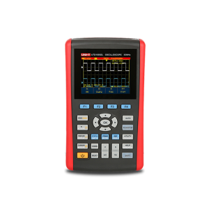
To troubleshoot a signal, connect the probe to the test point, adjust the vertical and horizontal scales, configure triggering, and analyze the displayed waveform. UNI-T oscilloscopes provide intuitive controls and automatic measurement tools that simplify signal debugging and fault diagnosis.
An oscilloscope is used to observe, measure, and troubleshoot electrical signals across R&D, education, manufacturing, and field service. Typical tasks include verifying circuit behavior, debugging embedded systems, checking power-supply ripple, decoding serial buses (I²C, SPI, UART, CAN), and validating signal integrity. By showing the exact shape and timing of a signal, it helps engineers confirm a design works and locate faults quickly—the everyday scenarios UNI-T oscilloscopes are designed for.
A digital oscilloscope works by sampling an input signal, converting it to digital data with an analog-to-digital converter (ADC), and reconstructing it as a waveform on screen. The signal enters through a probe, passes through vertical scaling and the ADC, and is stored in acquisition memory. A trigger stabilizes repetitive waveforms so the display stays still, letting you measure voltage and timing accurately—the core acquisition path in every UNI-T digital oscilloscope.
An oscilloscope can measure a wide range of signal parameters, including amplitude (peak-to-peak, RMS), frequency, period, rise and fall time, pulse width, duty cycle, and phase difference between channels. Many models add automated measurements, statistics, FFT/spectrum analysis, and serial-bus decoding. These capabilities let engineers characterize both analog and digital behavior from one instrument—automated measurement and decoding features you’ll also find across UNI-T oscilloscopes.
As a rule of thumb, choose an oscilloscope with bandwidth at least 5× the highest frequency component of your signal, and a sample rate at least 5× that frequency. For digital signals, the scope’s rise time should be 3–5× faster than the signal’s rise time to keep timing error under about 2%. Applying these ratios ensures the captured waveform reflects the real signal—and UNI-T’s oscilloscope range spans multiple bandwidth tiers to match different signal needs.
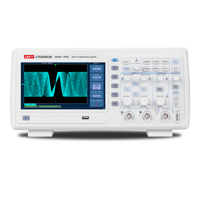
An oscilloscope (also known as scope, oscope, or O-scope) is a test instrument that displays how an electrical signal changes over time, plotting voltage on the vertical axis and time on the horizontal axis. Engineers use it to visualize waveforms and measure amplitude, frequency, and timing, revealing glitches and distortion a multimeter cannot show. Most modern oscilloscopes are digital, capturing signals as sampled data for measurement and analysis. UNI-T builds digital oscilloscopes on this same principle across a range of bandwidths.
The detector range is the span of values the instrument can measure while staying inside its stated accuracy. Readings outside that span are reported but are not covered by the accuracy specification.
Under normal workshop conditions a twelve-month calibration interval is sufficient. Shorten it to six months if the instrument is used daily, transported frequently, or operated outside 10–30 °C.
Yes, within the ingress-protection rating printed on the housing. Avoid direct rain and condensing humidity, and allow the instrument to reach ambient temperature before taking readings.